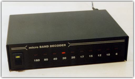
SWITCH OUTPUTS
The micro Band Decoder has ten (10) switched outputs.
These outputs are high side "source" provided by power transistors and are
capable of driving all micro Antenna Switches as well as switches by several
other manufacturers.
Reliability of the whole band decoder can be dramatically improved by
optional Relay Board. The Relay Board can optionally be configured by jumper to
provide a contact closure to ground for antenna switches like the Top Ten Devices "Six Way" antenna relay box.
Each output can be configured to be ON or OFF for each band by microHAM
Device Configurator software. With Device Configurator, antenna configurations can be changed
very easily without soldering or rewiring controls. Simply change the configuration with
Device COnfigurator, store the new configuration into Band Decoder and forget it.
LOGIC OUTPUTS
micro Band Decoder has for (4) band data outputs.
These outputs are BCD encoded according to the following table.
|
O\B
|
160
|
80
|
60
|
40
|
30
|
20
|
17
|
15
|
12
|
10
|
6
|
|
A
|
1
|
0
|
1
|
1
|
0
|
1
|
0
|
1
|
0
|
1
|
0
|
|
B
|
0
|
1
|
1
|
1
|
0
|
0
|
1
|
1
|
0
|
0
|
1
|
|
C
|
0
|
0
|
0
|
0
|
1
|
1
|
1
|
1
|
0
|
0
|
0
|
|
D
|
0
|
0
|
1
|
0
|
0
|
0
|
0
|
0
|
1
|
1
|
1
|
Outputs levels are TTL max. 100mA source. These outputs ALWAYS
carry current band information and are in addition to the switch outputs.
The primary use of the logic outputs are for the YAESU FL-7000 and QUADRA
control options and for optional BAND PASS FILTERS interfaces.
CW and PTT OUTPUTS
The rear panel contains RCA jacks for CW and PTT.
Each output is an OPEN COLLECTOR transistor capable of handling 30V/100mA.
CW and PTT can be derived from COM port (shared with radio control) with RTS = PTT and DTR = CW or from
a Parallel (LPT)
port connected to the ACC connector. The CW and PTT signals can be disabled
for frequencies out of the amateur bands.
SET
An external SPST switch can be plugged into this
jack to allow manually selecting between two antennas (for example: a high
monoband antennas and a low triband antenna) on a band. See application note 30.
INTERFACES
micro Band Decoder includes built-in level converters for all radios,
IF-232, FIF-232, CI-V and RS-232. With micro Band Decoder you do not need a separate level
converter for your radio.
PC
The band decoder needs to be connected only when
you want to configure or reconfigure band decoder. Configuration is stored in EEPROM
which that you not need to configure band decoder on each power up.
Even though micro Band Decoder does not require a computer for operation, logging software can control rig through
micro Band Decoder. In that case, micro Band Decoder will provide a level
converter plus CW and PTT drive to the radio and obtain frequency (band)
information from the data returned for the radio to the logging program.
Software functions:
Principles of operation:
The band decoder can decode the current operating frequency by serial
communication with radio or by 4-bit band data input. The 4-bit (BCD) band
data is generally used by only Yaesu radios and is required by most band
decoders.
So how does micro Band Decoder operate in CAT serial mode?
micro Band Decoder is connected between computer serial port
and radio serial port. It functions in one of two modes: Monitoring Mode and Polling Mode.
If the computer is OFF or not running a logging application, micro
Band Decoder is in Polling Mode. Every 500 mS it will poll the radio for the current operating
frequency. If logging software is running, and the software polls the radio on a regular
baisis, the Band Decoder provides a level converter between the computer and radio and listens
to the data from the computer and radio. micro Band Decoder will extract the current
frequency form this monitored data. In this mode Band Decoder never modifies the data.
If the computer does not poll for frequency, the Band Decoder will break the computer to radio
communication every 5 second to poll the radio for frequency information.
When the current
frequency is received, the band decoder will return to monitoring mode. If the computer fails
to poll for five seconds, band decoder will automatically switch to polling mode and continue
to poll until the logging software resumes polling. With the first computer poll,
the band decoder
automatically switches to monitoring mode.
FREQUENCY BAND SPLIT
Within each band two antennas can be switched based
on frequency. For example, you can select different antennas for 80m and
75m or you could use the outputs to switch additional capacitors or an inductor
tap for an antenna matching network.
The frequencies and outputs can be defined in the
microHAM Device Configurator.
MANUAL BAND SELECTION
Automatic band decoding can be overridden by external BCD
switch attached to the ACC connector or an external switch can be used to
manually select up to four different outputs per band. This function must
be selected in the microHAM Device Configurator.
VFO A VFO B SPLIT
The Band Decoder respects the frequency of both VFOs. Band outputs are
selected based on the VFO used for transmitting. If you will work
cross band split, TX VFO frequency antennas will be used.
SPECIAL PIN
micro Band Decoder has a single "special
purpose" TTL output. This pin is brought out to the BAND DATA OUTPUT.
Split Info Output:
If this option is checked, the band decoder generates
a TTL low (ground) if the operating frequency is inside lower window in the band map and a high
(+5V) if the current frequency is in the higher window of the band map.
Support IC-PW1:
If this option is checked, the band decoder generates signals
for an Icom IC-PW1 automatic PA. The PAICPW1 or one of the BPF options must be used.
The PAICPW1 option will allow an Icom PW1 to automatically track the band changes on
the radio regardless of type. Kenwood or Yaesu radios can be used and the PW-1 will automatically switch to correct band.
This option can also be used to allow a SteppIR antenna to track the operating
frequency even if the logging software does not poll the radio.
Support IC-2KL , IC-4KL:
If this option is checked, the band decoder generates signals
for an Icom IC-2KL or IC-4KL automatic PA. The PAICKL1 or one of the BPF
options must be used. This option generates correct band select voltage and reference for
these amplifiers.
Pulse generation:
If this option is checked, micro Band Decoder can
generate positive or negative pulse of variable length on every output (band) change
or frequency change larger than xx kHz. This can be used as a automatic signal for automatic
amplifiers to retune on every antenna change or large move in frequency.
MultiLock:
Prevents two micro Band Decoders from selecting the same band simultaneously.
Copyright � microHAM America, LLC
webmaster: W4TV